Topics
- Number Systems:
- Binary, Octal, Decimal, and Hexadecimal number systems.
- Complements of numbers (1’s complement, 2’s complement).
- Weighted and Non-weighted codes (BCD, Gray code, Excess-3 code).
- Boolean Algebra:
- Basic theorems and properties.
- Switching functions: Canonical (SOP, POS) and Standard forms.
- Algebraic simplification of Boolean expressions.
- Digital Logic Gates:
- AND, OR, NOT, NAND, NOR, XOR, XNOR gates.
- Universal gates (NAND, NOR).
- Multilevel NAND/NOR realizations.
Number Systems in Digital Electronics
In digital electronics, number systems are used to represent and manipulate numerical data. The most common number systems include:
- Binary (Base-2)
- Octal (Base-8)
- Decimal (Base-10)
- Hexadecimal (Base-16)
Each system has a different base (radix) and is used in different computing applications.
1. Binary Number System (Base-2)
- Uses only two digits: 0 and 1.
- Fundamental system in digital circuits (since computers work with ON/OFF states).
- Each digit is called a bit (Binary Digit).
- Example:
Applications:
- Used in processors, memory, and digital logic circuits.
2. Octal Number System (Base-8)
- Uses 8 digits: 0 to 7.
- Convenient for representing 3-bit binary numbers (since ).
- Example:
Applications:
- Early computing systems (now less common).
- Sometimes used in file permissions (Unix/Linux).
3. Decimal Number System (Base-10)
- Uses 10 digits: 0 to 9.
- The standard system for human counting.
- Example:
Applications:
- Everyday arithmetic, financial calculations.
4. Hexadecimal Number System (Base-16)
- Uses 16 digits: 0 to 9 and A (10), B (11), C (12), D (13), E (14), F (15).
- Represents 4-bit binary numbers compactly (since ).
- Example:
Applications:
- Memory addressing, color codes (HTML/CSS), assembly language.
Conversion Between Number Systems
| Conversion Type | Method |
|---|---|
| Binary ↔ Decimal | Use weighted positional expansion (powers of 2). |
| Octal ↔ Binary | Group 3 bits per octal digit. |
| Hexadecimal ↔ Binary | Group 4 bits per hex digit. |
| Decimal ↔ Binary | Repeated division by 2 (for integer part). |
| Decimal ↔ Hex/Octal | Divide by 16/8 and collect remainders. |
Example Conversions
-
Binary to Decimal:
-
Decimal to Binary:
(Remainder 1)
(Remainder 0)
(Remainder 0)
(Remainder 1)
(Remainder 1)
→ Read backwards: -
Binary to Hexadecimal:
→ Group into 4 bits: → -
Hexadecimal to Binary:
→ , →
Summary Table
| Number System | Base | Digits | Binary Grouping | Example |
|---|---|---|---|---|
| Binary | 2 | 0,1 | - | |
| Octal | 8 | 0-7 | 3 bits | |
| Decimal | 10 | 0-9 | - | |
| Hexadecimal | 16 | 0-9, A-F | 4 bits |
Why Different Number Systems?
- Binary: Used by computers (simplest for digital logic).
- Octal/Hex: Compact representation of binary (easier for humans).
- Decimal: Natural for human counting.
CC
Weighted and Non-Weighted Codes in Digital Electronics
In digital systems, binary codes are used to represent numbers, letters, or symbols. These codes can be classified into two main categories:
- Weighted Codes
- Non-Weighted Codes
Each type has different properties and applications in digital circuits and computing.
1. Weighted Codes
- Each bit position has a specific weight (like in traditional binary numbers).
- The decimal equivalent is obtained by summing the weighted bits.
- Examples:
- Binary Coded Decimal (BCD)
- 8421 Code
- 2421 Code
- Excess-3 Code (XS-3) (partially weighted but has a bias)
(a) Binary Coded Decimal (BCD)
- A 4-bit code where each decimal digit (0-9) is represented by its 4-bit binary equivalent.
- Weights: 8, 4, 2, 1 (like standard binary).
- Invalid codes: 1010 (10) to 1111 (15) are unused.
| Decimal | BCD (8421) |
|---|---|
| 0 | 0000 |
| 1 | 0001 |
| … | … |
| 9 | 1001 |
Example:
in BCD → 0101 0011 (5 = 0101, 3 = 0011)
Applications:
- Digital displays (7-segment LEDs).
- Financial and calculator systems.
(b) 2421 Code
- A self-complementing weighted code (9’s complement can be obtained by inverting bits).
- Weights: 2, 4, 2, 1.
- Example:
(since )
Applications:
- Used in some arithmetic circuits.
2. Non-Weighted Codes
- No positional weights are assigned to bits.
- Used for error detection, sequencing, and encoding.
- Examples:
- Gray Code (Reflected Binary Code)
- Excess-3 Code (XS-3) (has a fixed bias but is non-weighted in structure)
(a) Gray Code
- Only one bit changes between consecutive numbers.
- Prevents glitches in digital circuits (e.g., encoders, Karnaugh maps).
| Decimal | Binary | Gray Code |
|---|---|---|
| 0 | 0000 | 0000 |
| 1 | 0001 | 0001 |
| 2 | 0010 | 0011 |
| 3 | 0011 | 0010 |
Conversion (Binary → Gray):
- MSB remains the same.
- XOR each bit with the next higher bit.
Example:
Binary: → Gray:
→ Gray Code = 1111
Applications:
- Rotary encoders (position sensing).
- Error correction in digital communication.
(b) Excess-3 Code (XS-3)
- A biased code where each digit is represented by BCD + 3.
- Non-weighted but derived from BCD.
- Self-complementing (9’s complement is obtained by inverting bits).
| Decimal | BCD (8421) | Excess-3 |
|---|---|---|
| 0 | 0000 | 0011 |
| 1 | 0001 | 0100 |
| … | … | … |
| 9 | 1001 | 1100 |
Example:
in XS-3 → BCD (0101) + 3 (0011) = 1000
Applications:
- Older computing systems.
- Some arithmetic operations (simplifies subtraction).
Comparison: Weighted vs. Non-Weighted Codes
| Feature | Weighted Codes (BCD, 8421) | Non-Weighted Codes (Gray, XS-3) |
|---|---|---|
| Bit Position Weight | Yes (e.g., 8-4-2-1) | No |
| Arithmetic Use | Common (e.g., BCD adders) | Rare (except XS-3) |
| Error Detection | No | Yes (Gray code reduces glitches) |
| Sequential Changes | Multiple bits may change | Only one bit changes (Gray) |
Key Takeaways
- Weighted Codes (BCD, 8421, 2421) → Used in arithmetic operations.
- Non-Weighted Codes (Gray, XS-3) → Used in sequencing, error detection.
- Gray Code → Prevents glitches in digital transitions.
- Excess-3 → Simplifies subtraction in some cases.
Boolean Algebra in Digital Electronics
Boolean algebra is the mathematical foundation of digital logic circuits. It deals with binary variables (0 and 1) and logical operations (AND, OR, NOT). Below is a structured breakdown of key concepts:
Basic Theorems and Properties
Boolean algebra follows fundamental laws similar to conventional algebra but with binary operations.
(a) Fundamental Operations
| Operation | Symbol | Expression |
|---|---|---|
| AND | or none | |
| OR | ||
| NOT | or |
(b) Boolean Postulates
- Identity Law
- Null Law
- Idempotent Law
- Inverse Law
- Commutative Law
- Associative Law
- Distributive Law
- De Morgan’s Theorem
(c) Duality Principle
- Any Boolean expression remains valid if:
- and are swapped.
- and are swapped.
Example:
→ Dual is .
Switching functions: Canonical (SOP, POS) and Standard forms
1. Switching Functions
A switching function is a Boolean expression that defines the output of a digital circuit based on its input variables. It can be represented as:
Example:
2. Canonical Forms
Canonical forms are unique and standardized ways of representing Boolean functions using minterms (for SOP) or maxterms (for POS).
(a) Sum of Products (SOP) Form (Minterm Canonical Form)
- Represents a function as a sum (OR) of minterms (AND terms).
- A minterm is a product term where all variables appear exactly once (either in true or complemented form).
- Each minterm corresponds to a row in the truth table where the output is 1.
Example:
Consider a function with the truth table:
| A | B | F |
|---|---|---|
| 0 | 0 | 1 |
| 0 | 1 | 0 |
| 1 | 0 | 1 |
| 1 | 1 | 1 |
The SOP form is: (OR of all minterms where )
Minterm Notation:
(where )
(b) Product of Sums (POS) Form (Maxterm Canonical Form)
- Represents a function as a product (AND) of maxterms (OR terms).
- A maxterm is a sum term where all variables appear exactly once (either true or complemented).
- Each maxterm corresponds to a row in the truth table where the output is 0.
Example:
Using the same truth table as above:
| A | B | F |
|---|---|---|
| 0 | 0 | 1 |
| 0 | 1 | 0 |
| 1 | 0 | 1 |
| 1 | 1 | 1 |
The POS form is: (Only one maxterm where , i.e., )
Maxterm Notation:
3. Standard Forms
Standard forms are simplified versions of canonical forms where not all variables need to appear in every term.
(a) Standard SOP Form
- A simplified version of the canonical SOP.
- Each product term may not contain all variables.
Example:
(Not all terms have all variables.)
(b) Standard POS Form
- A simplified version of the canonical POS.
- Each sum term may not contain all variables.
Example:
(Not all terms have all variables.)
Key Differences: Canonical vs. Standard Forms
| Feature | Canonical Form | Standard Form |
|---|---|---|
| Uniqueness | Unique for a given truth table | Not unique (multiple possible forms) |
| Completeness | All variables appear in every term | Some variables may be missing |
| Complexity | More complex (more terms) | Simplified (fewer terms) |
3. Algebraic Simplification of Boolean Expressions
Simplification reduces the number of logic gates required in a circuit.
(a) Techniques
-
Using Boolean Theorems
- Apply Distributive, De Morgan’s, and Identity Laws.
- Example:
-
Consensus Theorem
-
Karnaugh Maps (K-Maps) (Graphical method for 2-6 variables).
(b) Example Simplifications
-
Simplify
- (since )
- (Absorption Law)
-
Simplify
- (Distributive Law)
Summary Table
| Concept | Key Points |
|---|---|
| Boolean Theorems | Identity, Null, Distributive, De Morgan’s Laws. |
| Canonical Forms | SOP (minterms), POS (maxterms). |
| Standard Forms | Simplified SOP/POS. |
| Simplification | Boolean algebra rules, K-Maps. |
Applications
- Logic gate minimization (fewer transistors, lower power).
- Digital circuit design (adders, multiplexers).
- Error detection and correction.
Digital Logic Gates: Fundamentals and Applications
Logic gates are the basic building blocks of digital circuits. They perform Boolean operations on binary inputs (0 and 1) to produce a single output. Below is a detailed breakdown of logic gates, universal gates, and their implementations.
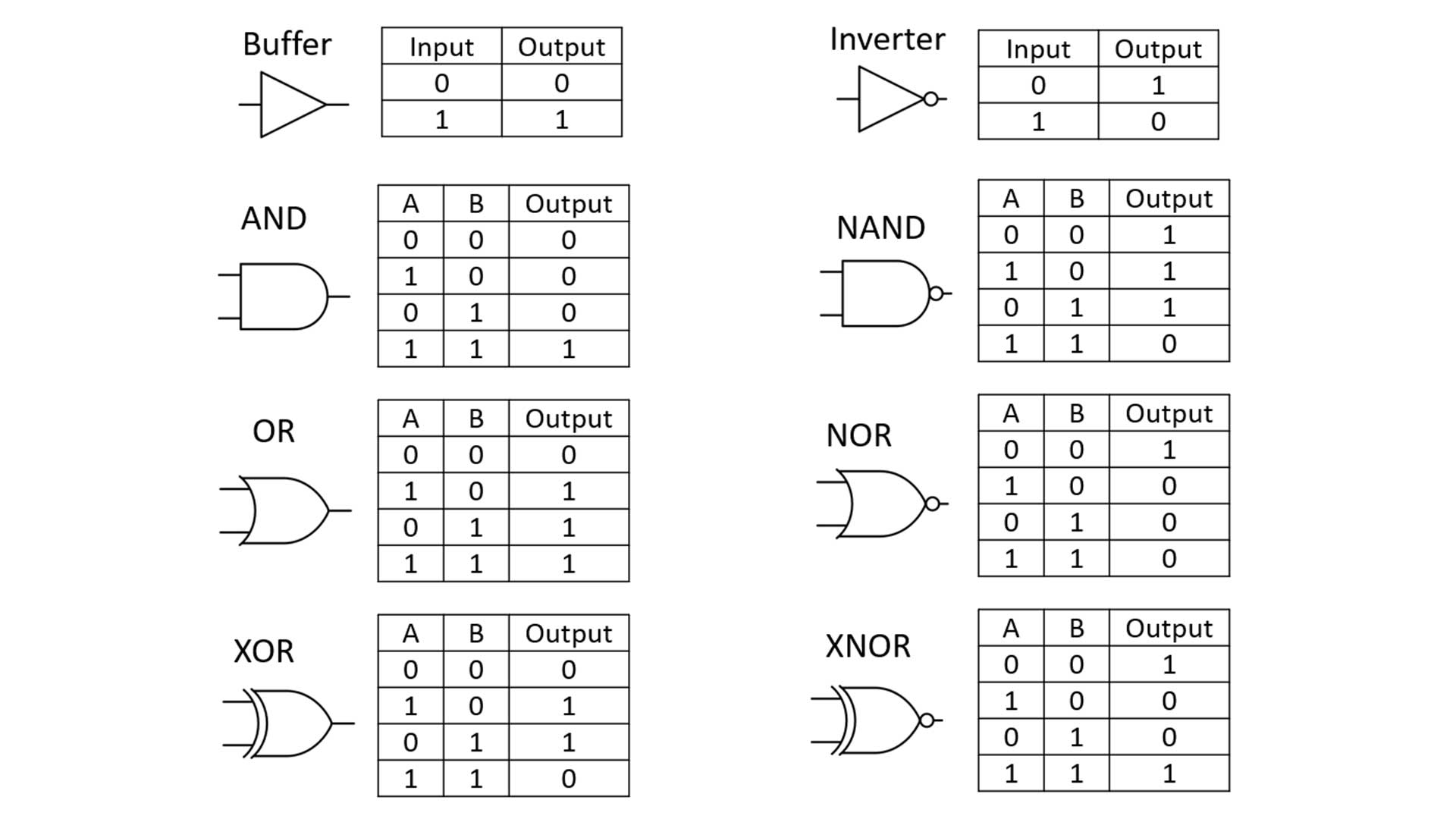
1. Basic Logic Gates
(a) AND Gate
- Truth Table:
| A | B | Y = A·B |
|---|---|---|
| 0 | 0 | 0 |
| 0 | 1 | 0 |
| 1 | 0 | 0 |
| 1 | 1 | 1 |
- Function: Output is 1 only if all inputs are 1.
(b) OR Gate
- Truth Table:
| A | B | Y = A+B |
|---|---|---|
| 0 | 0 | 0 |
| 0 | 1 | 1 |
| 1 | 0 | 1 |
| 1 | 1 | 1 |
- Function: Output is 1 if at least one input is 1.
(c) NOT Gate (Inverter)
- Truth Table:
| A | Y = A’ |
|---|---|
| 0 | 1 |
| 1 | 0 |
- Function: Output is the complement of the input.
(d) NAND Gate (NOT-AND)
- Truth Table:
| A | B | Y = (A·B)‘ |
|---|---|---|
| 0 | 0 | 1 |
| 0 | 1 | 1 |
| 1 | 0 | 1 |
| 1 | 1 | 0 |
- Function: Output is 0 only if all inputs are 1.
(e) NOR Gate (NOT-OR)
- Truth Table:
| A | B | Y = (A+B)‘ |
|---|---|---|
| 0 | 0 | 1 |
| 0 | 1 | 0 |
| 1 | 0 | 0 |
| 1 | 1 | 0 |
- Function: Output is 1 only if all inputs are 0.
(f) XOR Gate (Exclusive-OR)
- Truth Table:
| A | B | Y = A⊕B |
|---|---|---|
| 0 | 0 | 0 |
| 0 | 1 | 1 |
| 1 | 0 | 1 |
| 1 | 1 | 0 |
- Function: Output is 1 if inputs are different.
(g) XNOR Gate (Exclusive-NOR)
- Truth Table:
| A | B | Y = A⊙B |
|---|---|---|
| 0 | 0 | 1 |
| 0 | 1 | 0 |
| 1 | 0 | 0 |
| 1 | 1 | 1 |
- Function: Output is 1 if inputs are the same.
2. Universal Gates
Universal gates can implement any Boolean function without needing other gates. The two universal gates are:
(a) NAND Gate as Universal
- Can implement NOT, AND, OR:
- NOT:
A NAND A = A' - AND:
(A NAND B) NAND (A NAND B) = A·B - OR:
(A NAND A) NAND (B NAND B) = A+B
- NOT:
(b) NOR Gate as Universal
- Can implement NOT, AND, OR:
- NOT:
A NOR A = A' - OR:
(A NOR B) NOR (A NOR B) = A+B - AND:
(A NOR A) NOR (B NOR B) = A·B
- NOT:
3. Multilevel NAND/NOR Realizations
(a) NAND-NAND Realization (SOP Form)
- Convert Sum of Products (SOP) to NAND gates only.
- Example:
→ Implement as:AB → NAND + NAND (invert twice) CD → NAND + NAND Final OR → NAND (De Morgan’s Law)
(b) NOR-NOR Realization (POS Form)
- Convert Product of Sums (POS) to NOR gates only.
- Example:
→ Implement as:A+B → NOR + NOR (invert twice) C+D → NOR + NOR Final AND → NOR (De Morgan’s Law)
Summary Table
| Gate | Function | Universal? |
|---|---|---|
| AND | A·B | No |
| OR | A+B | No |
| NOT | A’ | No |
| NAND | (A·B)‘ | Yes |
| NOR | (A+B)‘ | Yes |
| XOR | A⊕B | No |
| XNOR | A⊙B | No |
Applications
- NAND/NOR: Used in IC design (simplifies fabrication).
- XOR: Used in adders, parity checkers, cryptography.
- Universal Gates: Help in minimizing circuit cost.