View PDF
Introduction to Cellular Networks
Mobile communications have drastically evolved over the decades. The first generation (1G) in the 1970s and 1980s used analogue signals. The 1990s introduced 2G (GSM), which brought the world into digital cellular communications.
By switching to digital, networks could use digital source coding, channel coding, and Forward Error Correction (FEC) to vastly improve transmission quality and spectral efficiency. It also introduced air interface encryption for better security, seamless international roaming, and Location-Based Services (LBS).
Core Mobile Network Functionalities:
Modern cellular networks handle much more than just calls. They manage: multimedia services, congestion and flow control, Quality of Service (QoS) management, addressing, routing, handovers, authentication, media access control, multiplexing, modulation, and encryption.
The Cellular Concept & Coverage:
Networks provide coverage across various scales: PAN (Personal Area), MAN (Metropolitan Area), WAN (Wide Area), and GAN (Global Area).
-
SDMA (Space Division Multiple Access): To cover large areas, the geographic landscape is divided into hexagonal “cells” (up to 35 km in radius).
-
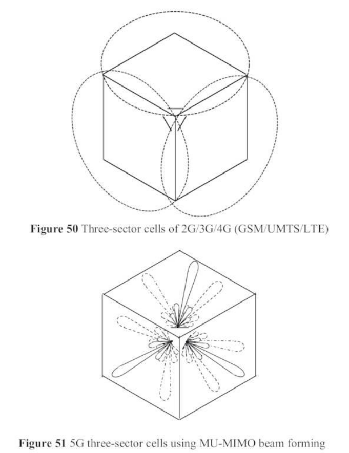
Sectoring: Each cell is typically split into three sectors (approx. 120° each) to optimize radio coverage and reduce interference.
-
Frequency Reuse: Frequencies used in one cell/sector are carefully planned and reused in distant cells to avoid interference while maximizing capacity.
-
Beamforming (5G Evolution): Traditional 2G/3G/4G antennas blindly cover a 120° sector. 5G introduces massive MIMO multi-user beamforming, where the antenna beam dynamically points directly at user “hot spots.” This prevents wasting transmit power on empty areas and drastically improves spectral efficiency.
1. GSM (2G) and Its Evolution
GSM (Global System for Mobile Communications) was initially designed for basic voice telephony and Short Message Services (SMS).
Access Technology:
GSM uses a combination of SDMA, FDMA (Frequency Division Multiple Access), and TDMA (Time Division Multiple Access).
-
FDMA: Carrier frequencies are spaced 200 kHz apart.
-
TDMA: Each carrier frequency is split into 8 time slots, which users take turns utilizing.
| Parameter | GSM900 | GSM1800 | GSM1900 |
|---|---|---|---|
| Uplink | 890–915 MHz | 1710–1785 MHz | 1850–1910 MHz |
| Downlink | 935–960 MHz | 1805–1880 MHz | 1930–1990 MHz |
| Channel spacing | 200 kHz | 200 kHz | 200 kHz |
| No. of channels | 124 | 374 | 299 |
| Time multiplex | 8 full-rate time slots, 16 half-rate time slots | same as CSM900 | same as CSM900 |
| Time slot duration | 577 µs | same as CSM900 | same as CSM900 |
| Bits per time slot | 114 | same as CSM900 | same as CSM900 |
| Frame length | 4.615 ms | same as CSM900 | same as CSM900 |
| Gross rate full-rate | 22.8 kbps | same as CSM900 | same as CSM900 |
| Gross rate half-rate | 11.4 kbps | same as CSM900 | same as CSM900 |
| Modulation scheme | GMSK | same as CSM900 | same as CSM900 |
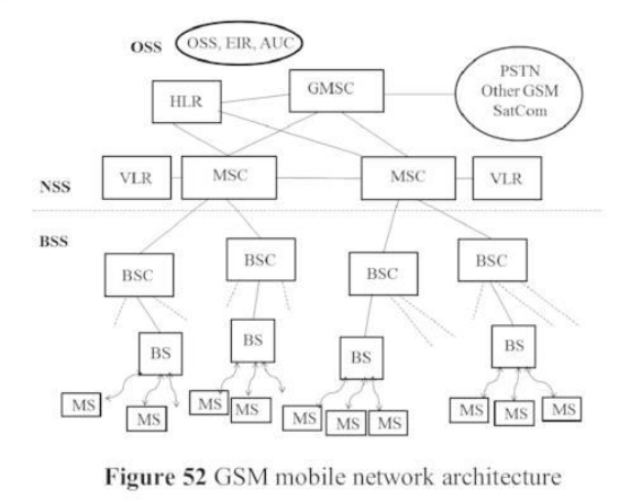
GSM Network Architecture:
The network is divided into three primary sub-systems:
-
BSS / RSS (Base Station / Radio Sub-System): Manages radio propagation and the “air interface” ().
-
MS (Mobile Station): The user’s handheld terminal.
-
BTS (Base Transceiver Station): The actual antennas and radio equipment.
-
BSC (Base Station Controller): The hub that controls multiple BTSs and manages radio resources before connecting to the core network via the ‘A’ interface.
-
-
NSS (Network Sub-System / Core Network): Manages call switching, mobility, and interconnection.
-
MSC (Mobile Switching Centre): The most important element. It handles switching, interworking (via Gateway MSC - GMSC), paging, call forwarding, mobility signaling, billing, and terminates the SS7 signaling system.
-
HLR (Home Location Register): The master database containing all subscriber profiles and data.
-
VLR (Visitor Location Register): A temporary database tracking users currently visiting the MSC’s coverage area.
-
-
OSS (Operation Sub-System): Manages network maintenance and security.
-
AUC (Authentication Centre): Generates security keys for user authentication.
-
EIR (Equipment Identity Register): Tracks mobile hardware (IMEI) to block stolen devices.
-
Evolution of GSM (2.5G and 2.75G):
-
HSCSD (High Speed Circuit Switched Data): Allowed a single user to use multiple time slots simultaneously, increasing data rates to 57.6 kbps. Only required a software update.
-
GPRS (Generalized Packet Radio Service): A major shift to Packet-Switched data (up to 171.2 kbps). It required new hardware in the core network: the SGSN (Serving GPRS Support Node) and GGSN (Gateway GPRS Support Node).
-
EDGE / EGPRS (Enhanced Data rates for GSM Evolution): Increased data rates (up to 70 kbps per time slot) by changing the modulation from GMSK to 8-PSK (which packs 3 bits per phase).
- Link Adaptation (LA): EGPRS can dynamically adapt its channel coding scheme (MCS-1 to MCS-9) within 100 ms based on current radio channel quality (e.g., C/I > 9 dB, BER < ).
-
EGPRS2: Pushed speeds further (up to 118.4 kbps) by using advanced 16-QAM and 32-QAM modulation and Turbo Coding.
2. UMTS (3G) and Its Evolution
UMTS (Universal Mobile Telecommunications System) introduced a completely new medium access technology: CDMA (Code Division Multiple Access). Instead of separating users by frequency or time slots, all users share a broad 5 MHz frequency band. Users are separated using unique mathematical codes called OVSF (Orthogonal Variable Spreading Factor) combined with scrambling codes.
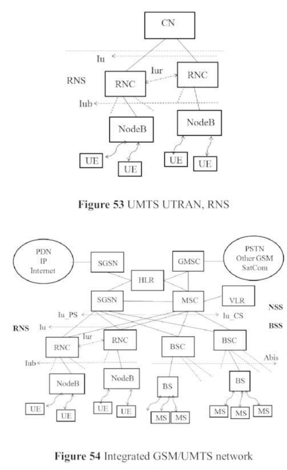
UMTS Architecture:
The UMTS radio network is called UTRAN (UMTS Terrestrial Radio Access Network). It runs parallel to the GSM network.
-
Node-B: The 3G equivalent of the BTS. It measures channel quality, handles inner-loop power control, and transmits data over the air.
-
RNC (Radio Network Controller): The 3G equivalent of the BSC, but much more powerful. It handles admission/congestion control, channel coding, outer-loop power control, handovers, and encryption.
-
Interfaces: The RNC connects to Node-Bs via the interface, and to other RNCs via the interface.
Core Network (CN) Domains:
The UMTS core relies on the GSM backbone but splits it logically:
-
CSD (Circuit Switched Domain): Handles voice calls using GSM components (MSC, VLR). Connects to UTRAN via the -CS interface.
-
PSD (Packet Switched Domain): Handles internet data using GPRS components (SGSN, GGSN). Connects to UTRAN via the -PS interface.
Key UMTS Features:
-
Soft Handover (Macro Diversity): In GSM, a phone drops the old cell before connecting to the new one (“hard handover”). In UMTS, a phone connects to the new Node-B while still connected to the old one. The user equipment (UE) uses a RAKE-receiver to process signals from multiple antennas. This redundancy drastically increases robustness and reduces fading.
-
Cell Breathing: In CDMA, a cell’s size is not just tied to transmit power; it depends heavily on interference caused by other users sharing the same frequency. As traffic load increases, interference increases, causing the Signal-to-Interference-and-Noise Ratio (SINR) to drop. Users at the cell edge lose connection first, making the cell “shrink.” If traffic load exceeds 75%, the cell becomes highly unstable. This is a major challenge for network planning.
Evolution of UMTS (HSPA):
-
HSDPA (High Speed Downlink Packet Access): Boosted speeds and lowered latency. It reduced the TTI (Transmission Time Interval) to 2 ms using a new MAC-hs layer. By using adaptive modulation (4-PSK up to 64-QAM) and Multiple Cell (Dual/Quad/Octa Cell) with MIMO antennas, real-world speeds reached 42 Mbps, with theoretical peaks up to 337.5 Mbps (Release 11).
-
HSUPA (High Speed Uplink Packet Access): Boosted upload speeds up to 5.76 Mbps (or up to 23 Mbps in later releases).
3. LTE (4G)
LTE (Long Term Evolution) was a paradigm shift to an All-IP (Internet Protocol) packet-switched network. Traditional circuit-switched voice calls were replaced by Voice over IP (VoIP) using the IMS (IP Multimedia Subsystem).
- Performance Targets: 100 Mbps (Downlink) / 50 Mbps (Uplink), with round trip latency < 10 ms. Bandwidth can be flexibly scaled from 1.5 MHz up to 20 MHz.
Access Technology:
LTE abandoned CDMA in favor of:
-
OFDMA (Orthogonal Frequency-Division Multiple Access): Used for the downlink (also used in WiFi and DVB-T).
-
SC-FDMA (Single Carrier FDMA): Used for the uplink. SC-FDMA has a much lower peak-to-average transmit power ratio, which saves battery life on the user’s mobile device.
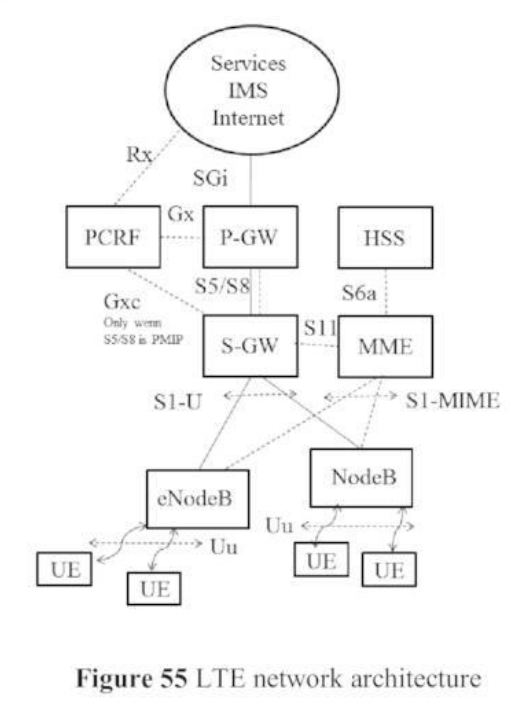
LTE Architecture (EPS - Evolved Packet System):
The LTE architecture simplifies the network into the UE, the E-UTRAN (Radio Access Network), and the EPC (Evolved Packet Core).
-
eNodeB: The LTE base station, encompassing functions of both the old Node-B and RNC.
-
EPC (Evolved Packet Core) Elements:
-
MME (Mobility Management Entity): The brain of the control plane. Handles authentication, security, mobility management, and subscriber profiles.
-
S-GW (Serving Gateway): The data plane router connecting the E-UTRAN to the core.
-
P-GW (Packet Data Network Gateway): The edge router that connects the EPC to the external internet.
-
PCRF (Policy and Charging Resource Function): Handles billing rules and Quality of Service (QoS) policies.
-
HSS (Home Subscription Server): The modern equivalent of the HLR, storing user subscription profiles and location data.
-
4. 5G Mobile Networks
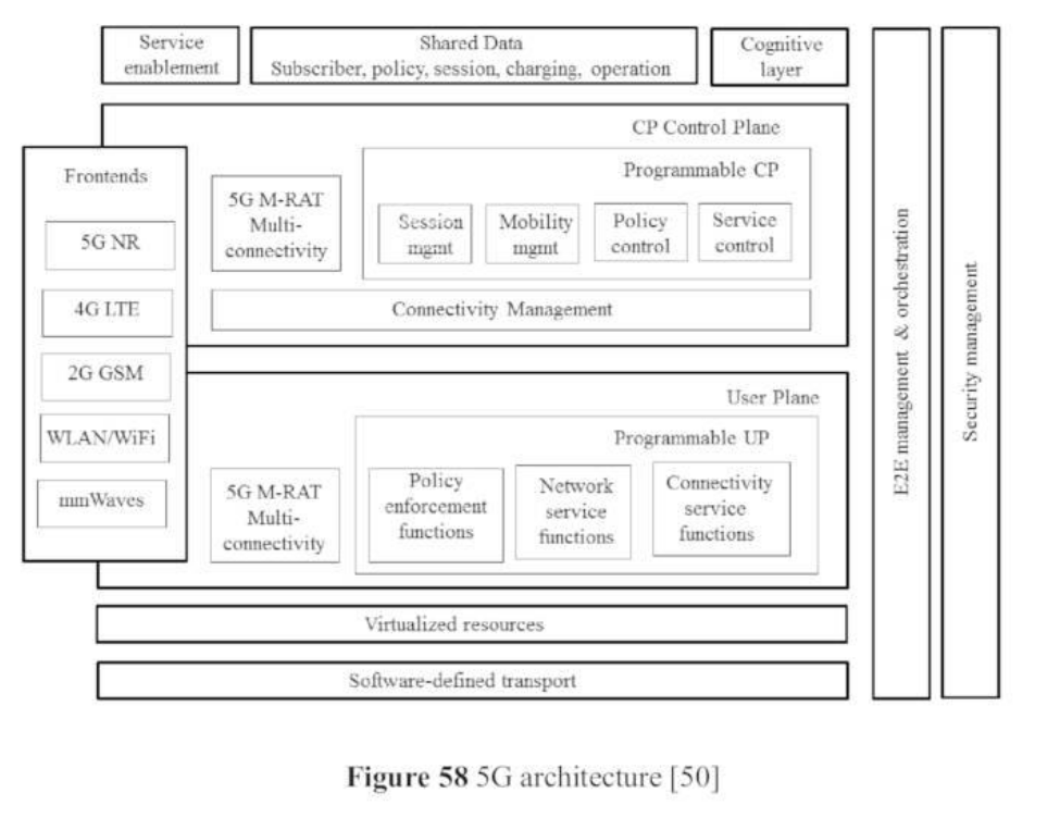
5G networks represent a leap forward in providing ultra-high bit rates, ultra-low latency (around 1 ms), massive scalability, and extreme energy efficiency. It integrates heavily with SDN (Software Defined Networking) and NFV (Network Function Virtualisation), allowing hardware to be replaced by programmable software.
Network Slicing:
Using SDN and NFV, 5G can create isolated, virtual “slices” over the exact same physical infrastructure. Each slice is tailored to specific QoS requirements (e.g., one slice configured for ultra-fast gaming, and another configured for low-power smart meters).

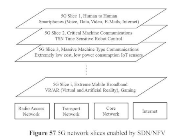
Basic 5G Service Classes:
-
eMBB (enhanced Mobile Broad Band): Focuses on high data rates for multimedia, AR/VR, video streaming, and enterprise applications.
-
mMTC (massive Machine Type Communications): Focuses on massive connection density for the Internet of Things (IoT), smart agriculture, and smart cities. Prioritizes low cost and extreme battery life (up to 10 years).
-
URLLC (Ultra-Reliable Low Latency Communications) / uMTC: Focuses on zero-delay, mission-critical services like autonomous driving (V2X), remote telesurgery, drone control, and industrial robotics.
New 5G Core Functionalities:
-
CUPS (Control and User Plane Separation): Allows scaling the control plane (signaling) independently from the user plane (data).
-
SBA (Service-Based Architecture): The core uses a cloud-native, micro-services approach (self-scaling and self-healing).
-
Edge Clouds: Computing power is moved closer to the base stations to reduce Round Trip Time (RTT) to a minimum.
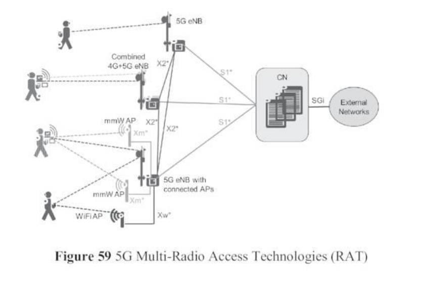
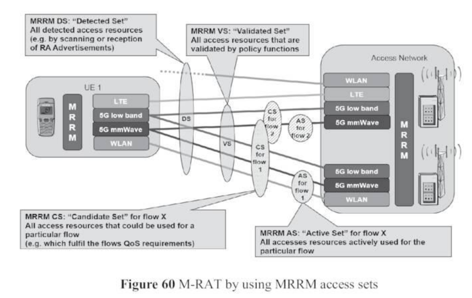
M-RAT (Multiple Radio Access Technology):
5G seamlessly blends multiple radio technologies (5G New Radio mmWaves, 4G LTE, WiFi, and even 2G GSM for voice backups). Network resources are dynamically shared and optimized using Multiple Radio Resource Management (MRRM).
- Simulations show mmWaves (e.g., 28 GHz) can use directional or three-sector antennas to provide massive bandwidth over short distances, seamlessly switching to LTE for broader coverage.
| Technology | Carrier Frequency | Bandwidth | BS TX Power | Typical Bitrate | Cell Radius | Delay |
|---|---|---|---|---|---|---|
| LTE | 0.9–3.5 GHz | 1.25–20 MHz | 46 dBm | 2–50 Mbps | 0.5–1.7 km | 100 ms |
| WLAN 802.11a-n | 2.4/5 GHz | 20–80 MHz | 23–30 dBm | 100–400 Mbps | 10–50 m | n.g. |
| WLAN 802.11ac | 5 GHz | 2–80 MHz | 23–30 dBm | 3.6 Gbps | 10–50 m | n.g. |
| 5G low band | 0.8–6.0 GHz | GHz | 15 dBm | 1 Tbps | 0.5 km | 3 ms |
| 5G high band | 6.0–90 GHz | GHz | 15 dBm | 1 Tbps | 0.5 km | 3 ms |
| Technology | rt-NB (Voice, Skype) | rt-NB (uMTC V2V, Control) | nrt-NB (mMTC IoT, Sensors) | rt-BB (Video Conversation) | nrt-BB (Streaming, Download) |
|---|---|---|---|---|---|
| LTE | x | x | |||
| WLAN/WiFi | x | x | x | ||
| 5G low band | x | x | x | x | x |
| 5G high band | x | x | x | x |
5G Security Requirements:
5G expands security needs far beyond 4G. It must protect against:
-
SMS/MMS-based DoS (Denial of Service) attacks, malware, and botnets on User Equipment.
-
Smart jamming of radio signals.
-
Location tracking via packet sequence numbers.
-
Unauthorized access due to weak “slice” isolation.
-
Threats to small cell nodes (femtocells) and signaling overhead overloads.
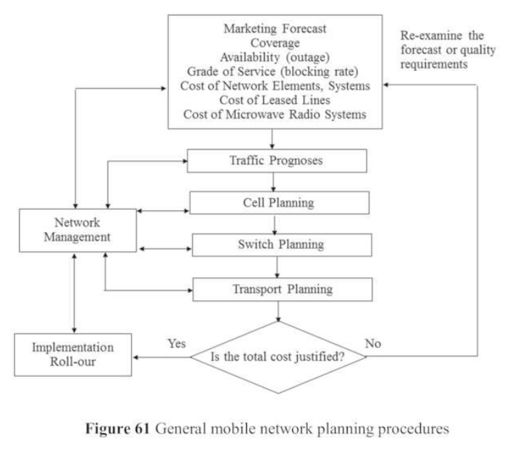
5. Mobile Network Planning Aspects
Network planning is a highly complex process balancing coverage, user density, service demands (voice, data, IoT), blocking probabilities, and capital costs.
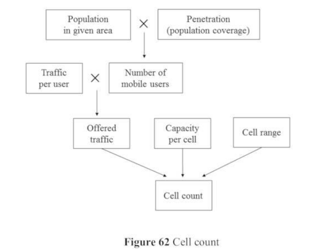
Traffic Forecasting & Cell Planning:
-
Traffic Modeling: Voice traffic intensity is measured in Erlangs.
-
Formula: (where = average call requests, = call duration, = users).
-
For multimedia data, the unit ETE (Equivalent Telephony Erlang) or simply Mbps/km² is used.
-
-
Nominal Cell Planning: Engineers use 3D geographic terrain software (accounting for mountains, buildings, forests) to predict Line of Sight (LOS) and multipath propagation.
-
Site Surveys & Drive Tests: Engineers visit proposed sites to verify the software’s nominal plan. After base stations are built, “drive tests” are conducted to tune the network and fix dead zones.
Grade of Service & Cell Sizing:
-
Erlang B Formula: Network capacity is designed so that the blocking probability ()—the chance a user gets a “network busy” signal—never exceeds 2% during peak busy hours.
-
Cell Scaling: In a rural area with 30 users/km², a single cell might cover 35 km. In an urban “hot spot” with 5,000 users/km², the heavy traffic load dictates that cells must be shrunk to tiny micro-cells (e.g., 0.2 km²) to provide enough capacity.
Radio Propagation & Signal Fading:
-
Okumura-Hata Model: Used to estimate signal loss ().
-
Urban Macro Cell:
-
Suburban Area:
-
Cell Area Approximation:
-
-
Multipath Fading: Radio waves bounce off buildings, arriving at the receiver at slightly different times, causing destructive interference.
- Rake Receivers: Solve this by estimating the phase delays of the bounced signals and shifting them so they superimpose constructively, saving the signal.
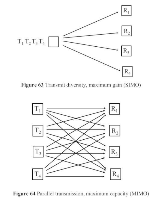
Antenna Diversity & Channel Capacity:
-
SIMO (Single Input Multiple Output): Provides space redundancy and receive diversity to combat fading.
-
MIMO (Multiple Input Multiple Output): Uses parallel transmission paths to vastly increase capacity and allows beam-forming to focus signals precisely on users, reducing interference.
-
Channel Capacity Formula: A standard channel’s capacity is . With MIMO antennas, capacity theoretically multiplies, greatly enhancing spectral efficiency.
Transport/Backhaul Network:
The connections between base stations and the core network must be virtually fail-proof.
-
Media: Uses Point-to-Point (PtP) microwave radio relay systems, leased lines, or optical fibers.
-
Protection Schemes: Networks are built in rings or meshes to provide redundancy (e.g., SNCP or MSP).
-
1:1 Protection: Reserves a specific percentage of capacity for recovery.
-
1+1 Protection (Hot Standby): Data is transmitted over both a primary and redundant path simultaneously. If the primary fails, the system instantly switches to the redundant path with zero perceivable outage to the users.
-
Links:
Unit 1 Information Theory and Communication Technologies
Unit 2 Wireless Communication Technologies
Unit 3 Cellular Mobile Networks
Unit 4 Free Space Optical Communications
Unit 5 Network Security and Management