View PDF
1. Optical Fibre
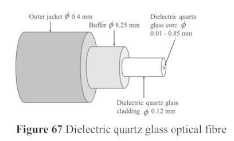
Since the invention of quartz glass fiber by Charles Kao, optical fiber has rapidly developed to become the most important and indispensable backbone of the modern internet and global multimedia transmission.
Key Characteristics & Advantages:
-
Material: Made of dielectric quartz glass.
-
Immunity: It has absolutely no interference or Electromagnetic Compatibility (EMC) problems.
-
Massive Bandwidth: A single optical channel can achieve bit rates up to 1 Tbps.
-
DWDM Technology: Using Dense Wavelength Division Multiplexing, 40 to 100 separate optical channels can be transmitted simultaneously over a single fiber, providing tremendous capacity compared to traditional copper wires or microwaves.
-
Network Scale: It is the unrivaled transport technology for all network sizes, including LAN (Local), MAN (Metropolitan), WAN (Nationwide), and GAN (Global Area Networks—such as transoceanic cables connecting continents).
2. Fiber Network Architectures (FTTC, FTTH, FTTBS)
To provide customers with internet speeds higher than 16 Mbps, the Signal-to-Noise Ratio (SNR) must be increased. This is done by replacing long, lossy twisted-pair copper wires with optical fibers. Optical fibers offer an extremely low attenuation (signal loss) of just 0.24 dB/km and are immune to electrical interference.
Depending on how close the fiber gets to the user, networks are classified into different architectures:
-
FTTC (Fibre to the Curb): * Optical fiber is extended from the backbone network to a termination unit very close to the customer’s premises (within 100 to 300 meters).
-
The final “last mile” connection into the home still uses existing copper wires.
-
Because the copper distance is so short, it supports high-speed VDSL (25 Mbps Download / 5 Mbps Upload) and VDSL2 (50 Mbps DL / 10 Mbps UL).
-
-
FTTH (Fibre to the Home):
-
The optical fiber is installed directly inside the home or office floor.
-
This is technically the perfect solution for maximum speed. However, replacing 100-year-old copper infrastructures requires tremendous construction, installation work, and high expenses.
-
Because of the cost, FTTH is currently prioritized in densely populated urban areas, while copper (xDSL) will remain the standard in rural areas for decades.
-
-
FTTBS (Fibre to the Base Station):
-
With the explosive data traffic demands of 5G and future 6G networks, standard microwave backhaul is no longer enough.
-
FTTBS brings optical fiber directly to the mobile base stations, making it an indispensable part of modern cellular networks.
-
3. Free Space Optical Communications (FSOC)
3.1 Background
Free Space Optical Communications (FSOC) transmits data by propagating infrared waves through free space (the air) instead of using a dedicated quartz glass fiber.
Advantages over Radio Frequency (RF) & Microwave:
-
No Cables Required: Connections can be established flexibly and quickly. It is ideal for disaster recovery, temporary events, or communicating with moving objects (like airplanes and satellites).
-
High Capacity: Offers higher bit rates and smaller device sizes compared to RF systems.
-
License-Free: The optical spectrum is license-free, avoiding the strict regulations and costs of RF spectrums.
Challenges:
-
Line of Sight (LOS): A strict visual contact between the transmitter and receiver is mandatory.
-
Pointing Errors: Transceivers must be aligned with extreme precision.
-
Atmospheric Interference: The signal is highly susceptible to absorption, scattering, and atmospheric turbulence.
3.2 Free Space Optical Link Subsystems
A complete FSOC system consists of three primary subsystems:
-
Transmitter: Modulates the incoming message onto an optical carrier (a laser beam). It consists of a modulator, an optical source (usually a laser diode), and a transmitting telescope which shapes the beam and tracks the receiver.
-
Channel: The atmosphere itself. It is the major limiting factor of FSOC. Conditions like snow, fog, and clouds change constantly with time and geography, heavily influencing signal strength.
-
Receiver: Recovers the transmitted data. It consists of a receiver telescope, a very sharp optical bandpass filter (to filter out background sunlight and noise), and a demodulator.
3.3 Channel Model with Different Factors
Several complex factors dictate how well an FSOC link performs through the atmosphere:
1. Wavelength Selection:
-
Eye Safety: Wavelengths between 400 nm and 1400 nm are hazardous as they focus directly on the human retina. Therefore, wavelengths of 1.5 µm and larger are preferred for terrestrial FSOC.
-
Atmospheric Windows: Gases in the atmosphere (like water, carbon dioxide, and ozone) absorb specific frequencies. Wavelengths are carefully chosen to fall into “windows” where absorption by these molecules is minimal.
2. Divergence and Free Space Loss:
-
The most significant loss is beam divergence—the natural spreading of the laser beam as it travels.
-
A narrow beam divergence is preferred, but this requires active beam tracking to keep the antennas perfectly aligned.
-
The Received Power () formula is:
(Where is transmitted power, and are the gains of the transmitter and receiver telescopes, and is free space path loss).
-
Higher wavelengths generally have lower free-space attenuation.
3. Weather Conditions & Scattering:
-
Fog (Mie Scattering): Fog consists of tiny particles that cause “Mie scattering.” The attenuation can be calculated using visibility range. Crucially, fog attenuation is dependent on the wavelength—larger wavelengths suffer less attenuation.
-
Rain and Snow: Consist of much larger particles. They cause deep signal fades, and this attenuation is not affected by the chosen wavelength.
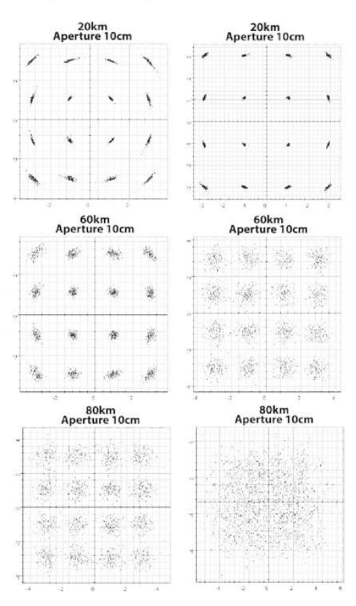
4. Atmospheric Turbulence:
-
Inhomogeneous (uneven) temperature and pressure in the air create “turbulent cells” or “eddies” with different refractive indexes.
-
When a laser hits these randomly distributed cells, it causes wave front distortion in phase and amplitude.
-
If the cells are larger than the beam, a phenomenon called beam wandering occurs, where the beam’s distribution angle physically shifts, potentially missing the receiver entirely.
5. Modulation Constraints:
-
Simulation results (e.g., using DP-QPSK or 16-QAM) show that high bit rates (like 100 Gbps) degrade rapidly and fail over long distances due to channel attenuation.
-
For larger distances, lower bit rates (like 10 Gbps) and lower-order modulation schemes must be used. To reach Tbps speeds, DWDM must be implemented over the free-space link.
4. Deep Space Optical Communications (DSOC)
DSOC is currently heavily investigated by space agencies like NASA and ESA to replace classical Radio Frequency (S, X, and Ka bands) for deep-space missions.
Advantages over RF:
-
Beam divergence is improved by a factor of 100.
-
Delivers much higher bit rates.
-
Drastically reduces the required size and weight of spacecraft antennas (apertures).
System Characteristics & Key Parameters:
-
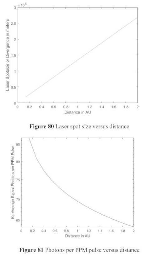
Distances: Designed to operate across vast distances up to 2.5 AU (Astronomical Units, where 1 AU = km).
-
Wavelengths & Power: Downlink (Space to Earth) uses a 1.55 µm laser diode at 5 Watts. Uplink uses a 1.064 µm laser at 5 kW.
-
Ground Receivers: Uses arrays of distributed optical telescopes (1m - 5m diameter) to aggregate the signal.
-
Photon Starvation: Over distances of 2.5 AU, the laser spot size expands massively. As a result, only a tiny handful of photons reach the receiver per pulse (photon starvation).
Overcoming DSOC Challenges:
-
M-ary PPM (Pulse Position Modulation): Instead of standard modulation, DSOC uses M-ary PPM (where M = 16 or 64). Each symbol is divided into ‘M’ time slots, and the entire energy of the laser is concentrated into just one of those slots. This creates a massive peak power burst that helps the signal punch through high background noise.
-
Combating Background Noise: Deep space receivers face severe noise from background sky radiance and the sun. This is mitigated by:
-
Using special polarization filters.
-
Using extremely narrow optical bandpass filters (e.g., 0.1 nm).
-
Spatial and temporal filtering.
-
-
Geiger-mode APD Receivers: The receiving telescopes use micro-lens Avalanche Photodiode (APD) arrays operating in “Geiger-mode”. These are so sensitive they can literally count individual incoming photons.
-
Error Correction: Because signal power is so incredibly weak at 2.5 AU, sophisticated Forward Error Correction (FEC) and channel coding are absolutely indispensable to piece the data back together.
Links:
Unit 1 Information Theory and Communication Technologies
Unit 2 Wireless Communication Technologies
Unit 3 Cellular Mobile Networks
Unit 4 Free Space Optical Communications
Unit 5 Network Security and Management